
Land Seismic Refraction
The Seismic Refraction method involves the measurement of travel times of seismic compressional waves (P-waves) that are generated at the surface.
Applications
- Bedrock mapping
- Mapping weathered zones
- Stratigraphic mapping
- Indicative material hardness for piling, tunnelling and excavation works
- Identification of fault / fractured zones
Method
The Seismic Refraction method involves the measurement of travel times of seismic compressional waves (P-waves) that are generated at the surface, propagate through the subsurface and return to the surface after being refracted at the interface between layers of contrasting seismic velocity. Seismic wave velocities are controlled by the fundamental parameters of elastic strength and density of the material it propagates through.
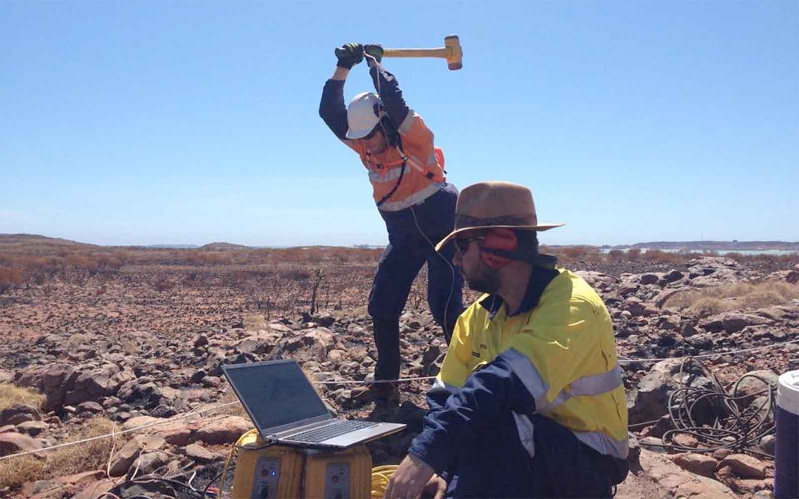
For near-surface investigations, seismic energy is generated on the surface using a sledgehammer. More powerful sources such as accelerated drop weights, downhole airguns, or explosives are required for deeper investigations. The generated seismic waves propagate through the subsurface at a certain velocity. On reaching a geological boundary marked by an increase in seismic velocity, at a specific angle the wave is critically refracted and travels along the top of the lower layer at a greater velocity. This generates head waves in the upper layer which return to the surface where it is detected as vibrations by a linear array of geophones spaced at regular intervals.
By measuring the travel times of these refracted waves from multiple source points to multiple receivers, the seismic refraction method can resolve lateral changes in the depth to the top of a refracting interface as well as the seismic velocity within it. Furthermore being related to elastic strength and density, the velocities calculated from a seismic refraction survey can be a useful guide to the rippability of rock for excavation.
Data Analysis & Presentation
Processing and analysing seismic refraction data can be carried out using a layered model assuming distinct refractive boundaries or tomographic approach assuming a gradual increase in seismic velocity with depth. Both approaches have benefits and are typically carried out in unison to generate the most detailed geological model possible.
The output is a cross-section showing lateral changes in the depth to the various refracting interfaces and the seismic velocities within them. When correlated with core logs, this information can be related to geological boundaries in the subsurface. This can be particularly useful for planning excavation with the depth to the different layers giving an idea of the quantity of rock needed to be removed and the seismic velocities giving an idea of the rock’s hardness and hence rippability.
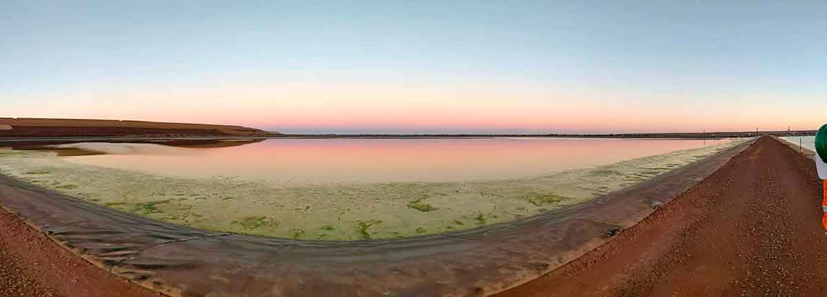
Tailings Management: Get in touch
Consider a 'Tailings First' approach for your facility and avoid creating a potentially catastrophic risk for the environment.
GBG combines industry-proven geophysical methods, geotechnical physical characterisation, hydrogeological modeling and assessment, and airborne methods for point-based data capture in assessing your requirements. Talk to us today for more information regarding this essential service for your tailings facility.
Case Studies
GBG has completed over 1000 projects since its conception with multiple stakeholders and countless clients. GBG is proud to showcase some of these projects.
Enquire Now
We look forward to discussing your project with you, please complete the form below or contact one of our offices directly.
Please note: GBG Group is compliant with the General Data Protection Regulation (GDPR). To learn more about how we collect, keep, and process your private information in compliance with GDPR, please view our privacy policy. *

Contact Us - NSW


Contact Us - WA