Electrical Methods
Half Cell Potential
Applications
- Determine probability and map extent of possible corrosion of steel reinforcement
Method
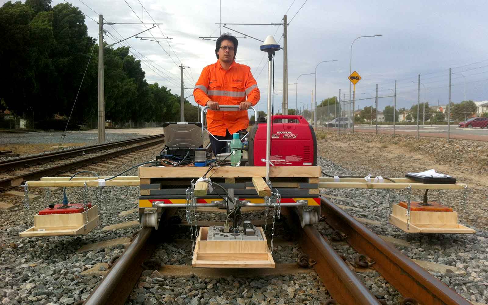
Half Cell Potential mapping exploits the electrical/corrosion activity between the half-cell created on the steel reinforcement. In general, where the half cell potential becomes very negative it indicates that there is a propensity for active corrosion. No inference can be made of the rate of corrosion.
The test equipment consists of a high impedance voltmeter connected between a half-cell reference electrode and the steel reinforcement which acts as the other half-cell. The circuit is completed by contacting the reference half-cell to the concrete surface through a wet sponge.
Measurements are taken at grid points across the create a contour map showing potential corrosion sites according to the ASTM method C876-09 “Corrosion Potential of Uncoated Reinforcement Steel in Concrete”. Before initiating a survey it is necessary to confirm the electrical continuity of the reinforcement throughout the survey area.

Data Analysis & Presentation
Half cell potential results show areas of potential corrosion.
Metal Mass Probe
Applications
- Determine the amount of corrosion in encased steel member, pipes or steel sections where the steel cannot be observed directly
Method
The metal mass probe uses the pulse induction method where the greater the amount of metal below the search head the longer the voltage decay. This information is converted to a voltage signal which is proportional to the mass of metal in the field. An estimate of the remaining metal can be made by direct comparison with uncorroded sections of the structure. The structure is scanned at a rate of approximately three readings per second and is recorded directly to a laptop computer for later analysis.
The MMP results are extremely sensitive to depth due to the field strength weakening with distance from the sensor. Changes in the metal cover depth must therefore be measured using Ground Penetrating Radar and a correction for depth is then applied.
Data Analysis & Presentation
Data are presented in tables and on CAD drawings where applicable.
Resistivity
Applications
- Chloride resistance of concrete and concrete permeability
- Indicate potential corrosion rate of reinforcement in concrete.
Method
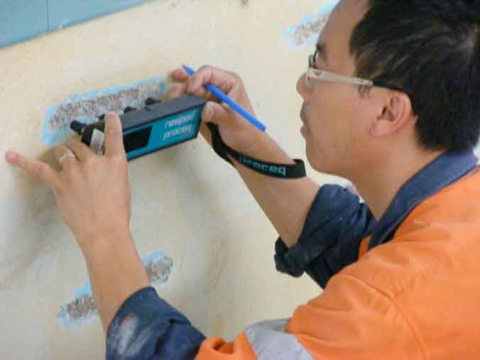
Whilst the half cell potential measurement is effective in locating regions of potential corrosion activity, it does not indicate the rate of corrosion. Resistivity measurements used in conjunction with the half cell potential technique can be used to determine the propensity for current flow between anodic and cathodic portions within the test area. A low resistance path between anodic and cathodic sites is associated with a higher rate of corrosion than a high resistance path.
Resistivity effects are due to an electrolytic process as a consequence of ionic movement in the aqueous pore solution of the concrete matrix. This therefore also provides a good estimate of the permeability of the concrete. The Wenner four-probe technique is generally adopted for resistivity measurement of in situ concrete following the AASHTO TP95-11 standard specifies a 38 mm probe space which is suitable for aggregate sizes up to 38 mm. The Resipod Geometric is supplied with a variable spacing probe that can accommodate larger aggregate sizes. It also allows the user to enter geometric correction factors via the ResipodLink software to give the correct resistivity reading directly on the instrument.

Tailings Management: Get in touch
Consider a 'Tailings First' approach for your facility and avoid creating a potentially catastrophic risk for the environment.
GBG combines industry-proven geophysical methods, geotechnical physical characterisation, hydrogeological modeling and assessment, and airborne methods for point-based data capture in assessing your requirements. Talk to us today for more information regarding this essential service for your tailings facility.
Case Studies
GBG has completed over 1000 projects since its conception with multiple stakeholders and countless clients. GBG is proud to showcase some of these projects.
Enquire Now
We look forward to discussing your project with you, please complete the form below or contact one of our offices directly.
Please note: GBG Group is compliant with the General Data Protection Regulation (GDPR). To learn more about how we collect, keep, and process your private information in compliance with GDPR, please view our privacy policy. *


