
Ultrasonic Methods
Ultrasonic Pulse Velocity
Applications
- Determine depths of surface cracks
- Calculate concrete stiffness and strength
- Determine the depth of fire-damaged concrete
- Detect defects within concrete eg. voiding, honeycombing
Method
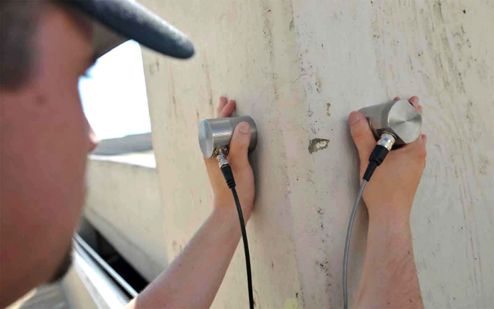
Ultrasonic Pulse Velocity (UPV) measurements record the time taken for an ultrasonic pulse of compression waves to travel through a known thickness of concrete. A piezoelectric transducer is held in contact with the concrete under test and a similar transducer, a set distance away, detected the arrival of the transmitted pulse. An electronic timing circuit measures the transit time of the pulse to allow the pulse velocity to be calculated. This velocity is directly proportional to the density and stiffness of the concrete and thus a concrete strength measurement can be estimated. This method is best used in conjunction with the Rebound (Schmidt) Hammer technique to provide a second source of information.
The most accurate results are often obtained from direct measurements through a structural element such as a beam or column. Care must be taken to avoid testing near reinforcement bards particularly those running parallel to the pulse path. The moisture condition of the concrete can also affect the result. This method can also be used to detect defects within the concrete because the ultrasonic waves are poorly transmitted by air-filled cracks and voids. These obstructions increase in effective path length, resulting in a lower pulse velocity.
Data Analysis & Presentation
The pulse velocity is compared to the established criterion for concrete quality and is provided in tables and explained in the report.
Ultrasonic Tomography
Applications
- Identify voids, channels, rebar, inclusions, degradation, honeycombing and cracking within concrete
Method
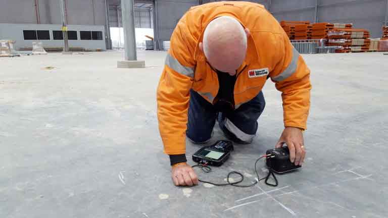
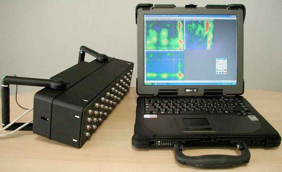
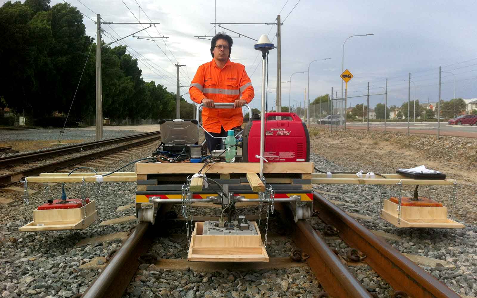
Ultrasonic Tomography including Multi-Impulse Ray Analysis (MIRA) is an acoustic technique that provides reflection imaging of the surface. The method consists of a synthetic aperture array of ultrasonic transducers (transmitters and receivers) that measure travel times for reflected shear wave pulses, propagated into a concrete medium. The method uses a new kind of ultrasonic transducer that does not require a coupling gel. Forty-eight dry tip transducers (MIRA system) are placed in an array that allows a 350 mm by 50 mm swathe of information to be collected every 5 seconds.
The transducers induce high-frequency shear wave pulses (adjustable between 25 and 85 kHz) into the concrete from the surface. Each array element measures the travel times of any reflected shear waves between the different array elements. This allows both the shear wave velocity and target depth to be determined. Using this information it can then image internal defects such as voids or honeycombing that will disrupt and reflect the induced shear waves. Shear wave energy will not pass through gases or liquids within voids or cracks and therefore is mostly reflected in such anomalies.
The unit is moved progressively along the element being tested and 20-100 mm intervals depending on the resolution required. The software records the information and can produce a 3D image that can be up to 2000 mm deep, 350 mm wide and as much as 10 m long in a single file. The software is then able to plot the relative amplitude of the reflected wave at the source of the reflection according to the selected colour scale.
Data Analysis & Presentation

Ultrasonic Tomography Section
(Stepped concrete slab 210 mm, 330 mm, 450 mm & 570 mm thick containing 50 mm diameter hollow ducts. Note the shadow below each duct)

Two images above from the MIRA ultrasonic system collected from the heavily reinforced caissons in the figure below. The pale blue areas are voids / honeycombing around and behind steel reinforcing
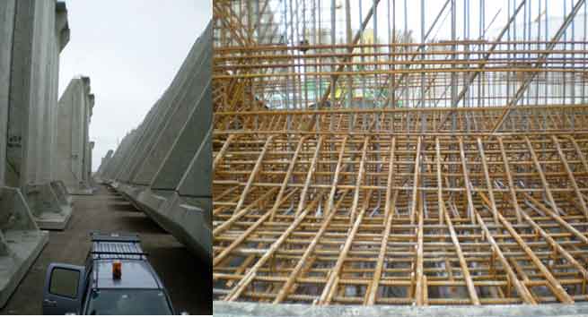
Photographs of caissons and internal reinforcement.
Modified Shock Testing
Applications
- Integrity testing of rock bolts and anchors
- Measure the length of anchor bolts
- Detect deficiencies in load capacity due to loss of section from corrosion or defects in the grout
Method
A stress wave is induced down the bolt using 3 to 5 lateral blows of a small hammer near the end of the bolt. A receiving velocity transducer held against the end of the bolt detects the axial waveform from the stress wave echoes and is recorded via an analogue to digital converter.
Data Analysis & Presentation
The signal is analysed in the frequency domain using a fast Fourier transform. Models for various criteria such as mechanical admittance, frequency spectra and velocity are all used to determine the integrity of the bolt under analysis.
Ultrasonic Thickness Gauge
Applications
- Measure the thickness of metal e.g. flanges, pipe, boiler tube, steel light pole
Method
Ultrasonic Thickness Gauge uses the pulse-echo principle similar to the Ground Penetrating Radar technique. A short ultrasonic pulse is transmitted into the material by a probe (transducer). The pulse travels through the material under test until it encounters an interface such as air or liquid at the back of the park, where the pulse has reflected the probe. This reflection is called the back-wall echo. A calibration block is also used to calibrate the probe for each material tested.
Data Analysis & Presentation
The time needed for the pulse to make the round trip is divided by 2 and multiplied by the velocity of sound in the material being tested. The result is the thickness of the material.
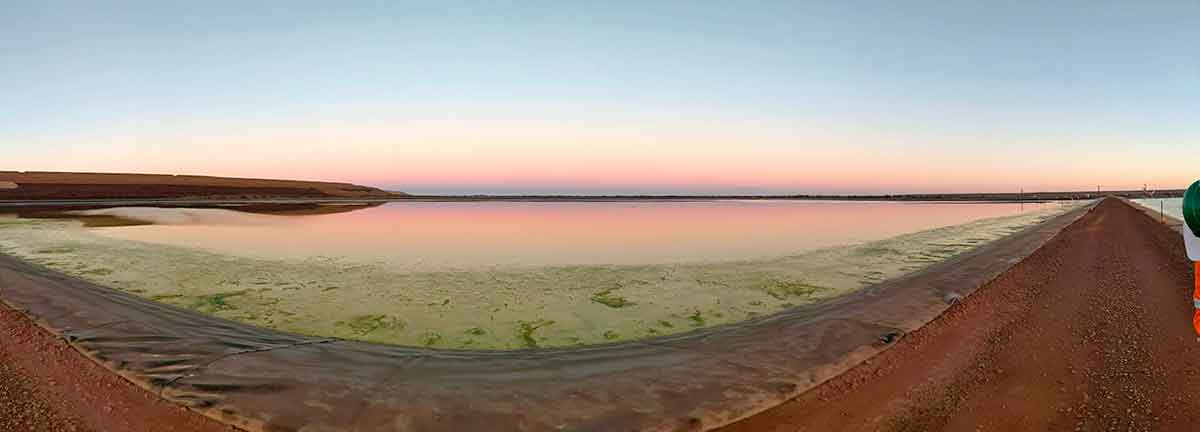
Tailings Management: Get in touch
Consider a 'Tailings First' approach for your facility and avoid creating a potentially catastrophic risk for the environment.
GBG combines industry-proven geophysical methods, geotechnical physical characterisation, hydrogeological modeling and assessment, and airborne methods for point-based data capture in assessing your requirements. Talk to us today for more information regarding this essential service for your tailings facility.
Case Studies
GBG has completed over 1000 projects since its conception with multiple stakeholders and countless clients. GBG is proud to showcase some of these projects.
Enquire Now
We look forward to discussing your project with you, please complete the form below or contact one of our offices directly.
Please note: GBG Group is compliant with the General Data Protection Regulation (GDPR). To learn more about how we collect, keep, and process your private information in compliance with GDPR, please view our privacy policy. *

Contact Us - NSW


Contact Us - WA