
Ground Penetrating Radar for NDT
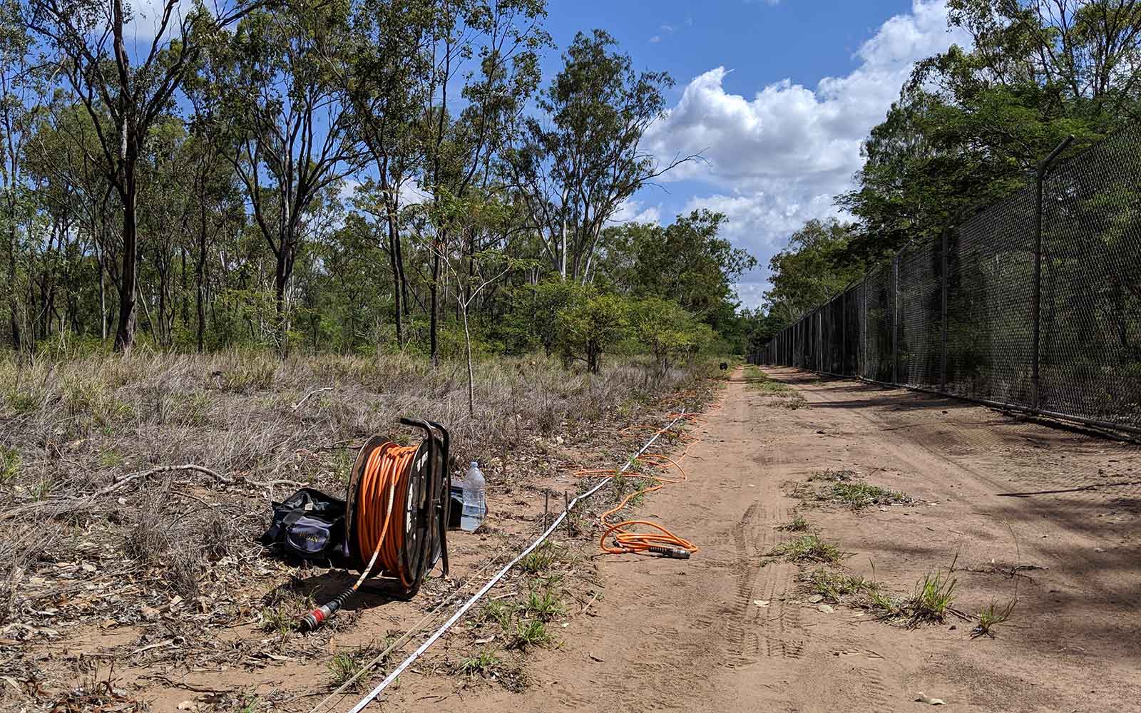
GPR always comes with us on these NDT investigations because it is versatile and gives us the insight to target areas with our other techniques.
Applications
- Image the internal structure of various materials
- Timber condition assessment eg. rot, termite damage
- Slab, beams and column details
- Bridges, buildings, concrete and masonry structures, approach slabs, void formers, tension ducts
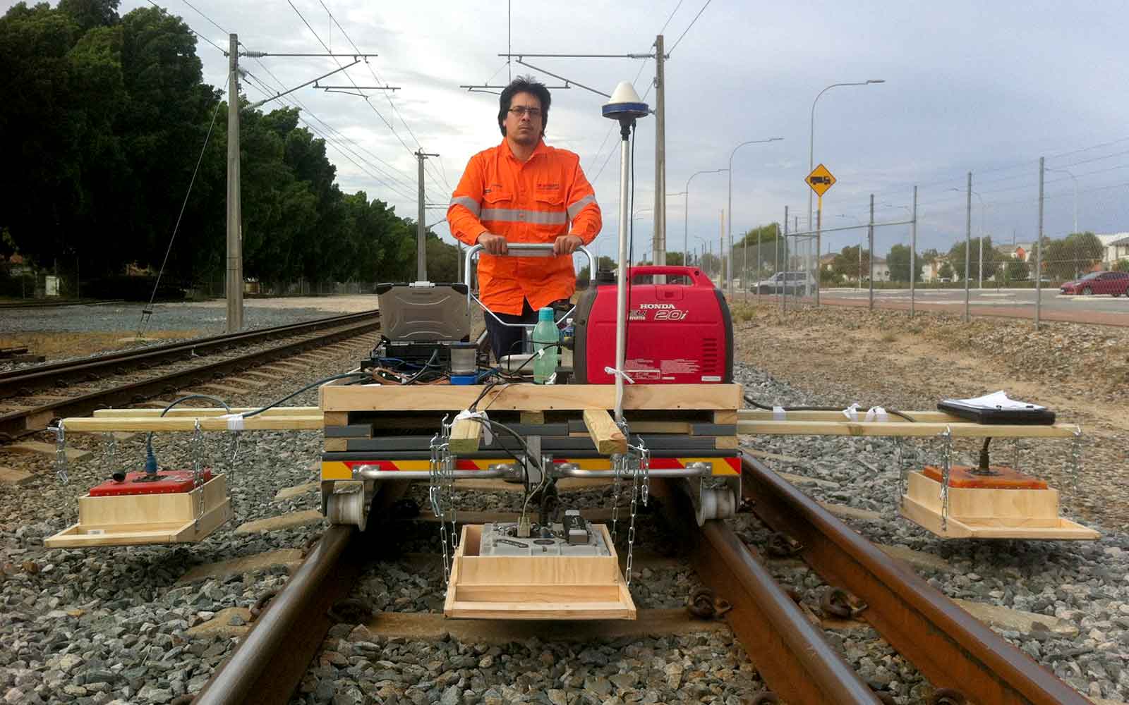
- Airport investigations of taxiways, railways, hardstands, footpaths, road pavement, asphalt, gravel and/or concrete
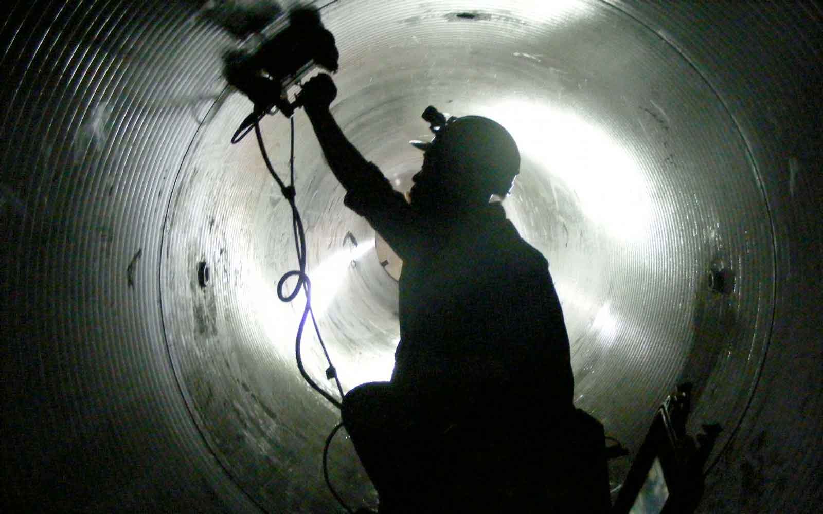
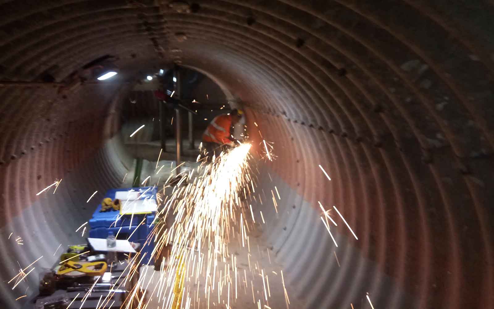
- Walls and tunnels construction details, crossbreaks, delamination, voiding, deconsolidation, settlement
- Penetrations to avoid cutting reinforcement and tendon ducts
- Reinforcement mapping, tendon duct location
- Tree root mapping
- Archaeology, locating graves / burials
- Foundation and footings
- Services/utility location
- Water/sewer infrastructure, pipe condition, leakage, voiding, underground storage tanks (USTs) location
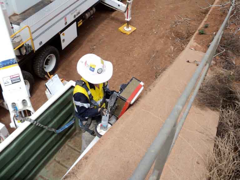
- Water retention structures
Method
Ground Penetrating Radar (GPR) uses reflections of transmitted radio wave pulses to create an image of the subsurface. A transmitting antenna is used to produce a continuous series of electromagnetic pulses that are reflected from boundaries and discontinuities within the material. These pulses propagate through the subsurface materials at a characteristic velocity and are reflected by any variations in material such as air gaps, moisture changes, embedded metal or different material layers. Any reflected energy is detected by a receiving antenna at the surface and recorded as individual traces or scans. This process is repeated continuously as the antenna is moved along the surface to build up an entire image profile or radargram along the survey line. The recorded reflections are analysed in terms of their signal shape, two-way travel time, amplitude and phase to determine the depth, location, size, orientation and relative material properties of subsurface objects.
The velocity with which a pulse travels through a material varies depending on the electrical properties of the material, which in turn are a function of the material’s chemical and physical properties. The amplitude of the reflected pulses that occur at these material transitions is related to the difference in characteristic velocity between the two different mediums and the sharpness of the transition relative to the wavelength of the transmitted wave. The greater the difference in material properties then the greater will be the amount of energy reflected.
The reflected signal strength diminishes with depth due to wave dispersion and electrical attenuation within the material. This limits the effective depth of penetration. The amount of signal loss increases at higher frequencies and varies with different materials. The size of the feature can be resolved depending on the wavelength of the transmitted wave. Higher frequency antennas have smaller wavelengths and therefore have higher resolution but also have shallower penetration depths. Therefore most surveys are compromised based on the target resolution and the required depth of penetration. Radar antennas transmit a radio pulse that produces a broadband signal at a particular centre frequency. This means that the resolution of the antenna diminishes the depth as the higher frequencies are absorbed nearer the surface. The maximise the energy transmitted most radar antennas are surface-coupled. For good coupling to existing the antenna must be at less than a quarter of a wavelength from the surface.
Surveys are generally carried out by profiling the structure over a grid of survey lines. This allows a 3D reconstruction of the arrangement, form and condition of the materials being investigated. Data can often be collected through a structural element (within limits) by profiling from one side. Generally, more than one layer of reinforcing is visible within such a profile. Information on the element thickness, reinforcement location, concrete cover, void location and the internal condition is often available from the same data profile. Access from both sides can provide clearer information, especially if the reinforcement is closely spaced. The advantage of this technique over a standard covermeter is the speed in which a large body of information, in the form of sections through the slab can be collected, the larger depths of penetration and higher resolution.
Data Analysis & Presentation
A plan-view of the results is provided in CAD drawings, with 2D slices of processed data of areas of interest on the objectives of the project.
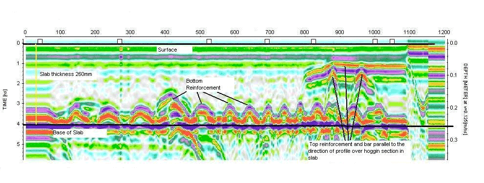
Example GPR profiles through suspended floor slab
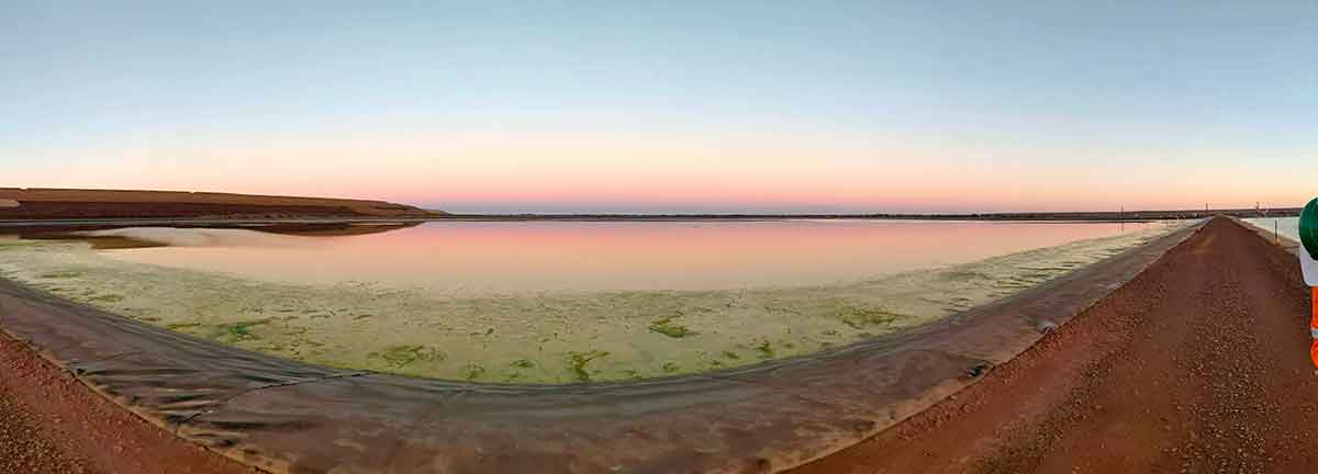
Tailings Management: Get in touch
Consider a 'Tailings First' approach for your facility and avoid creating a potentially catastrophic risk for the environment.
GBG combines industry-proven geophysical methods, geotechnical physical characterisation, hydrogeological modeling and assessment, and airborne methods for point-based data capture in assessing your requirements. Talk to us today for more information regarding this essential service for your tailings facility.
Case Studies
GBG has completed over 1000 projects since its conception with multiple stakeholders and countless clients. GBG is proud to showcase some of these projects.
Enquire Now
We look forward to discussing your project with you, please complete the form below or contact one of our offices directly.
Please note: GBG Group is compliant with the General Data Protection Regulation (GDPR). To learn more about how we collect, keep, and process your private information in compliance with GDPR, please view our privacy policy. *

Contact Us - NSW


Contact Us - WA