
Acoustic Methods
Impact Echo
Applications
- Assess dimensions and integrity of concrete and masonry.
- Map voids, honeycombing and discontinuities (cracks / delaminations).
- Assess bond quality between slab overlays or the degree of slab support for ground slabs based on signal amplitude and decay.
- Overlay thickness and slab thickness
- Crack depth and extent
- Map delamination
- Determine if tendon ducts are grouted
- Estimate compressive strength
- Determine thickness of tunnel lining, beams where access only from one side is possible
- Determine pavement thickness
Method
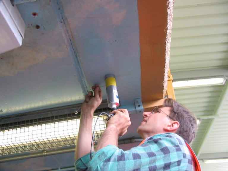
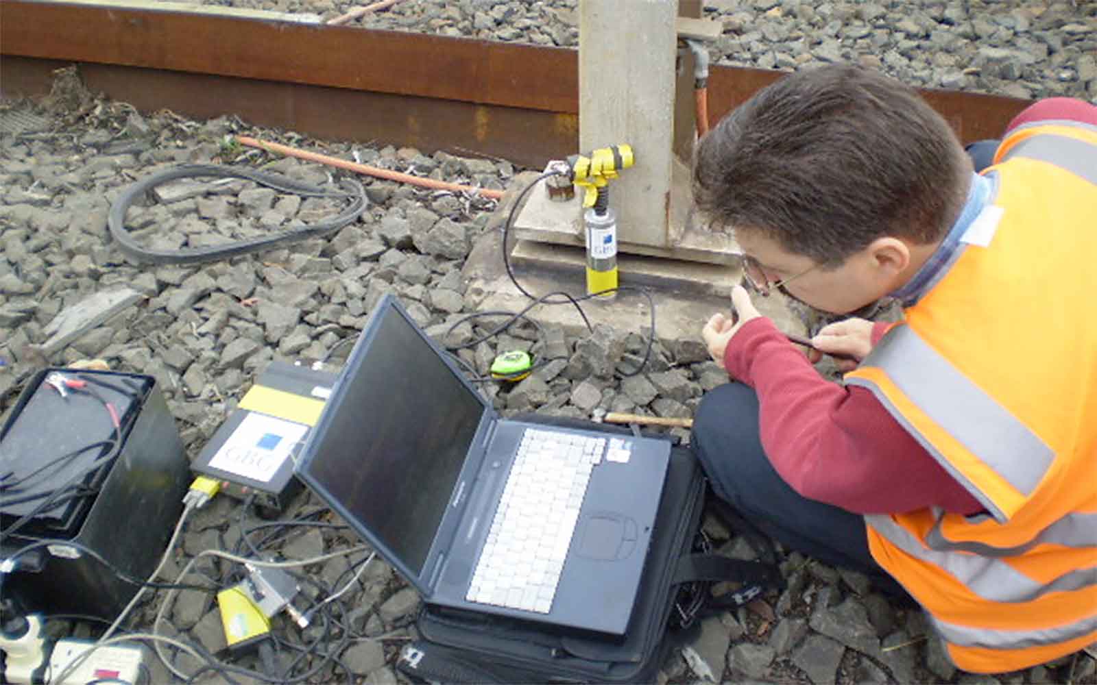
The Impact Echo method is where the surface of a structural element is struck with a steel ball of a specific size to induce a low-strain compression (P) wave into the material. The wavelengths of these stress waves are typically longer than the scale of natural inhomogeneities in concrete such as aggregate, air bubbles and micro-cracks. As a result, they are only weakly attenuated and multiple reflections of these waves excited natural resonances within the structure. The response is recorded by a sensitive acoustic transducer, placed on the surface near the impact point. The signal waveform is digitised and analysed in both the frequency and time domain to provide information on the element thickness and internal defects such as voids, honeycombing and discontinuities (cracks/delaminations). This technique can also be used to assess bond quality between slab overlays or the degree of slab support for ground slabs based on signal amplitude and decay.
The velocity of an acoustic wave within the material is proportional to its density and elastic modulus. This means that an estimate of the compressive strength can be made, and the presence of the reinforcement does not greatly affect the transmission or the signal thus allowing accurate assessments of defects even where steel is densely spaced. Used in conjunction with Ground Penetrating Radar, this technique can verify the continuity, integrity and mechanical properties of the structure at critical points, providing greater confidence in any conclusion resulting from the investigation.
Data Analysis & Presentation
Data is analysed in the frequency spectrum where the peak corresponds to the resonant frequency within the structure. The thickness of the slab or depth to the flaw can then be calculated based on the acoustic wave speed of the material. Thickness and condition assessments are usually presented in tables and/or on CAD drawings.
Slab Impulse Response
Applications
- Identify areas of voiding or loss of support below pavements
- Location of weak concrete
- Locate areas of delamination within the pavement
Method
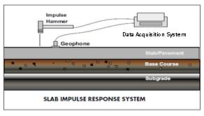
Slab Impulse Response is an acoustic method where a velocity transducer (or geophone) is mounted to the surface of the structure and an impact load is applied a few centimetres away. Both the force-time curve and the surface velocity-time curve are recorded. The system is designed to identify areas of voiding below pavements less than 400 mm thick or to quickly locate areas of delamination or weakness within the pavement. The average mobility (velocity/unit force) and flexibility (displacement/unit force) is calculated at each test point. Typically a grid of test points is recorded at a set increment to locate areas with relatively higher mobility or higher flexibility readings. Relatively low mobility and flexibility readings indicate that such areas are more solidly supported or bonded than those areas with relatively high mobility and flexibility.
Data Analysis & Presentation
Data is presented either in tables or as contour maps.
Sonic Echo / Impulse Response
Applications
- Determine length, continuity and structural integrity of a pile
- Characterise low strain pile-soil system response
Method
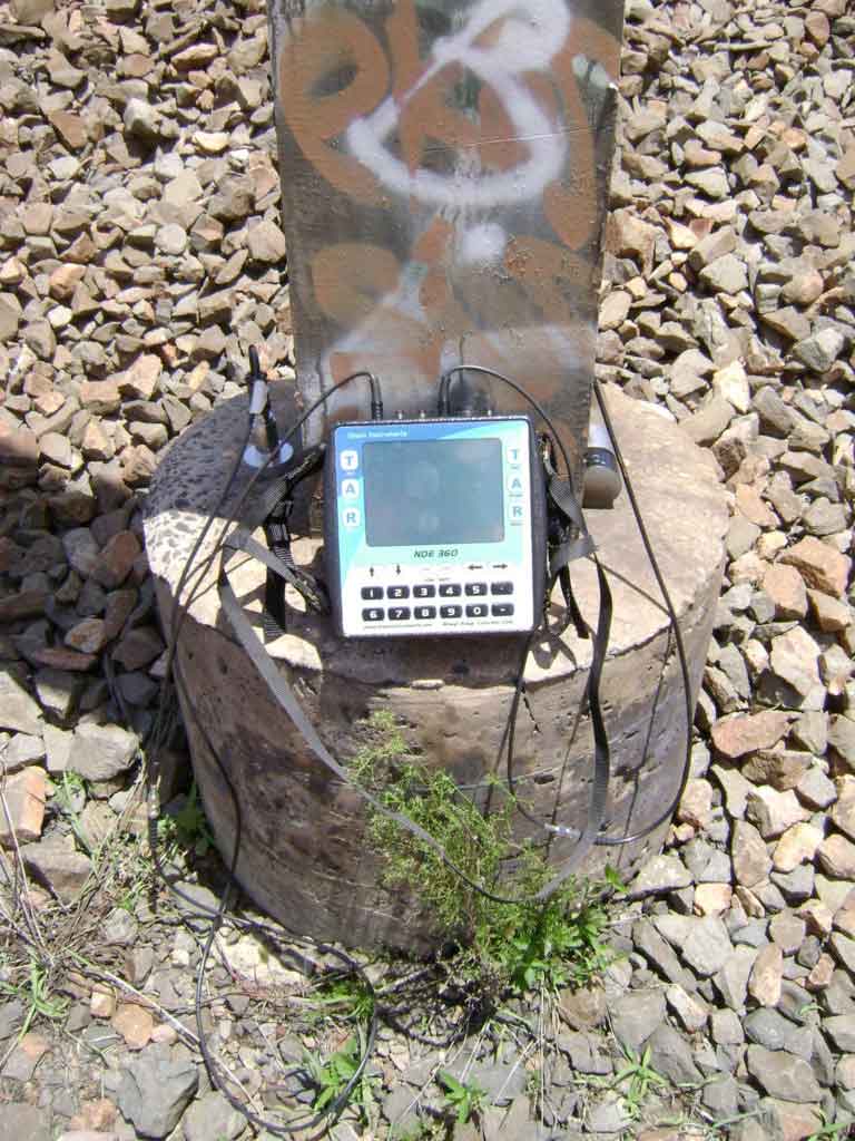
Sonic Echo is an acoustic method where a velocity transducer or accelerometer is mounted to the surface of the structure near the centre or along the edge of the pile. An impact is made near the centre of the pile, to which the echos from the bottom of the pile and any defects are recorded as a velocity-time trace. The depth (d) is calculated based on the time (t) taken for the reflected acoustic wave to return to the surface using the formula d = V*t/2, where V is the wave velocity. In the frequency domain, depth is calculated using the formula d = V/2Δf, where Δf is the difference in resonant frequency modes. Close agreement between the two methods can give a good indication of the degree of confidence in the result. For a good quality response, a depth estimate should be within + 10% of the actual depth.
In Impulse Response, the force-time curve is also recorded. This allows the structure's transfer function to be determined which provides further information about the structure. The coherence of the data can also be analysed to indicate data quality.
Data Analysis & Presentation
Data are presented in tables.
Tailings Management: Get in touch
Consider a 'Tailings First' approach for your facility and avoid creating a potentially catastrophic risk for the environment.
GBG combines industry-proven geophysical methods, geotechnical physical characterisation, hydrogeological modeling and assessment, and airborne methods for point-based data capture in assessing your requirements. Talk to us today for more information regarding this essential service for your tailings facility.
Case Studies
GBG has completed over 1000 projects since its conception with multiple stakeholders and countless clients. GBG is proud to showcase some of these projects.

Enquire Now
We look forward to discussing your project with you, please complete the form below or contact one of our offices directly.
Please note: GBG Group is compliant with the General Data Protection Regulation (GDPR). To learn more about how we collect, keep, and process your private information in compliance with GDPR, please view our privacy policy. *

Contact Us - NSW


Contact Us - WA